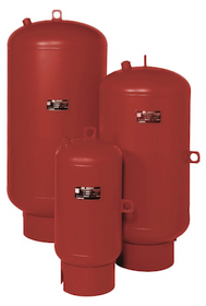
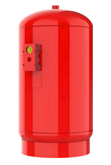
Bell & Gossett Pre-Charged Bladder & Diaphragm ASME Expansion Tanks
The Bell & Gossett ASME rated expansion tanks of series B-LA are bladder type pre-charged pressure vessels. It is designed specifically for absorbing the forces of expansion of heating or cooling system water. The process of absorption is done while maintaining proper pressure under different operating conditions. The B and G pre charged bladder tanks continue to set a high standard in the industry in terms of quality, reliable and performance. The performance of these tanks is proven in a number of different applications ranging from the well systems of the municipality to the sprinkler system in the golf course. The Bell & Gossett ASME Expansion Tanks have gained popularity in every field. It is also used in the pressure boosting stations.
Features:
- It provides the protection of the pump by reducing the surge and dampening the pressure spikes. It also offers a point of pressure and provides a minimum run time which further helps in pump protection.
- It is constructed, designed and tested within the standards of ASME Code Section VIII Division I
- It prevents water logging and also has a replaceable bladder.
- It also reduces the concentration of oxygen and increases the performance of the system.
- It provides rapid system response as well as adequate protection at the end of long pipe runs.
- It is pre-pressurized and sealed air charge.
- It is also corrosion-resistant and virgin polypropylene liner.
- It has the ability to control system shock as well as the pressure fluctuations when the system utilizes:
- 1. Solenoid
- 2. Check valves
- 3. Pumps and other control system.
- 4. Back flow preventers etc.
- It has a heavy duty, full acceptance and replaceable butyl bladder.
- The seismic restraints are available
- High pressure models are available of up to 125 PSI.
- The sight glass is also available
- Air from the system must not be allowed to enter the tank but should be purged to the atmosphere
- There is no requirement of Airtrol tank fitting.
- Shut off, drain valves or the tank purge valve must be installed in the pressurized expansion piping to check and recharge the tank air properly.
- The point of connection from the tank system represents the area of no pressure change. This means that the expansion tanks must be connected close to the suction side of the circulating pump of the system for proper system operation.
- In order to minimize the possibility of air and debris to enter the tank piping, the branch piping must be attached to the main. If it is connected to the horizontal main, don’t use the top and bottom positions which are 12’o clock and 6’o clock positions. The proper positions are the side connections.
- To change the pressure of the tank air charge, it is essential to isolate the tank circuit from the piping of the main system. A superior quality lock shield valve of gate type or TPV should be used for this purpose. The lock shield will eliminate the tampering during the normal system operation.
- With the lock shield valve, you should also install an automatic air vent as well as a pressure gauge in the piping.
- The calculations of tank sizing are based on rise of minimum temperature of the air in the tank.
- For the above purpose, an anti- thermosyphon loop should be formed in the piping to minimize the gravity effects of circulation in the tank.
- In order to replace the tanks, the tanks must be removed from the system.
- Note the location of the connection of system.
- Remove the pipe cap or plug from the system connection
- Remove the plug which covers the air charge valve.
- Prior to making a connection to the tank, use an accurate pressure gauge to check the tank and air charge. Ensure that the air pressure is equal to the minimum system pressure at the location of the tank.
- After ensuring the accuracy of the air charge, replace the plug over the air valve as indicated.
- The tank should now be piped to the system.
- Select the appropriate size of the pipe. The connection to each tank must have a TPV or lock shield gate valve to allow the insulation and removal whenever required. The valves should be filled into the connecting lines to ensure that the pump operation will not affect the operation of the valve.
The tank contains bladder and diaphragm to separate the air charge from the system water. The tanks are designed in order to absorb the expansion forces of heating or cooling the system water. The high Maximum operating temperature is 360-degree Fahrenheit.
The series B-LA tanks should be installed in a vertical position. They cannot be installed in a vertical position. The pressurized tank differs from the standard tank in the following major aspects:
- Air from the system must not be allowed to enter the tank but should be purged to the atmosphere
- There is no requirement of Airtrol tank fitting.
- Shut off, drain valves or the tank purge valve must be installed in the pressurized expansion piping to check and recharge the tank air properly.
Some general notes regarding piping:
- The point of connection from the tank system represents the area of no pressure change. This means that the expansion tanks must be connected close to the suction side of the circulating pump of the system for proper system operation.
- In order to minimize the possibility of air and debris to enter the tank piping, the branch piping must be attached to the main. If it is connected to the horizontal main, don’t use the top and bottom positions which are 12’o clock and 6’o clock positions. The proper positions are the side connections.
- To change the pressure of the tank air charge, it is essential to isolate the tank circuit from the piping of the main system. A superior quality lock shield valve of gate type or TPV should be used for this purpose. The lock shield will eliminate the tampering during the normal system operation.
- With the lock shield valve, you should also install an automatic air vent as well as a pressure gauge in the piping.
- The calculations of tank sizing are based on rise of minimum temperature of the air in the tank.
- For the above purpose, an anti- thermosyphon loop should be formed in the piping to minimize the gravity effects of circulation in the tank.
- In order to replace the tanks, the tanks must be removed from the system.
Installation:
- Note the location of the connection of system.
- Remove the pipe cap or plug from the system connection
- Remove the plug which covers the air charge valve.
- Prior to making a connection to the tank, use an accurate pressure gauge to check the tank and air charge. Ensure that the air pressure is equal to the minimum system pressure at the location of the tank.
- After ensuring the accuracy of the air charge, replace the plug over the air valve as indicated.
- The tank should now be piped to the system.
- Select the appropriate size of the pipe. The connection to each tank must have a TPV or lock shield gate valve to allow the insulation and removal whenever required. The valves should be filled into the connecting lines to ensure that the pump operation will not affect the operation of the valve.
Recent Posts
-
The Bell & Gossett Ecocirc XL Pump
The Bell & Gossett Ecocirc XL Pump: Innovation in Efficiency and ReliabilityIntroductionIn the w …18th Jul 2024 -
The Efficiency of The Bell & Gossett Series e-1510 Centrifugal Pump
Bell & Gossett Series e-1510 centrifugal pumps are one of the most efficient pumps in the market …22nd Mar 2023 -
How Important Is The Bell & Gossett Expansion Tank
Bell & Gossett expansion tanks are an important component in any hydronic heating or cooling system. …20th Feb 2023


